Sunday, July 29, 2012

"BATHALA" - PMX-003 MG The O vMatX Part VIII

Redesigning the redesign (or, more likely, refining the old one). Sometimes, simple is the best option. In this build, I tried to employ the simplest modification or build as I possibly can. In my previous update, I was able to make the base/arm of the wing as simple as I can, but, the more I worked on it and thought about it, the more stability problems can occur, especially since I was going to rely on a simple dual bar mechanism to hold a wing assembly more than 10 times its own weight. "

So another radical rethink was in order.  This time, I looked back at my original wing base design and assessed where it failed.

Posted Image

With all those articulation points being held up by a flimsy design, it was bound to fail, although it looked impressive at the time. Even though I was avoiding this, I wasn't prepared to sacrifice stability for simplicity. In this redesign, I've reconfigured the 4WD gears and the aluminum extenders to an optimum placement and positioning. I've used the same configuration (as I have for the old design) for the spine of the wing, as such, when one wing is turned in on direction, so will the other in the reverse direction, and these two hold each other in their relative angled positions with the wing's full weight (I haven't tried mounting both wings yet as I am still working on the other wing, but it does hold the weight of one wing so far). Instead of using plaplates as frame, I used a fiberglass bumper reinforcement to hold the gears in position, and mounted this on the O's backpack frame. This redesign removed the need for counter gears (flesh colored flat gears in the original design).

I've sandwiched 4 pieces of shaped WHIPS, bored a hole to snugly fit the gear's shaft, and superglued it into place, doing the same thing for the other side in reverse. The angled cut allows for a nice rotation range for the wing.

Posted Image

Posted Image Posted Image Posted Image


For the wing arm, I used those nifty 4WD aluminum extensions in a yin-yang configuration and placed gears/countergears at each end. One end attaches to the wing base, the other to the lower part of the secondary wing, making the design similar to an actual bird wing (as compared to the forced-wing design of the Wing Zero Custom). This allows the maximum rotation angle for either end. I've also customized hinges using 5mm beams as the the hinge shaft and 6mm hollow square beams as the hinge receptacle, encasing the latter in a square configuration to hold it in place (the hollow square beams are made with a different type of plastic and does not melt with cement). This gives the wing two articulation points on the Y-axis; one at the wing base, and the other at the lower wing.

Posted Image

Posted Image Posted Image


More later...

Saturday, July 28, 2012

The GBWC Philippines Regional Final "Twist"


It's on.  And the deadline's a month earlier than in previous years.  Last year was huge, with a lot of heavily modified entries making it into the mix.
click on the picture to reveal the twist

But, there's a new twist in the rules.  Aside from bringing the box to provide authentication, the manual must also be provided, PLUS, and here's where it can get hairy, kits used as entries MUST be bought from Toys R Us, with receipts.

Okay.  Nothing wrong with that on the marketing perspective since Toys R Us are basically forcing people to purchase kits so people can enter, but, like myself, there are a lot of people who start their entries early, hence have already bought kits.  I doubt this is a drive to prevent bootlegs from making it into the pool, since no one in his right mind would enter a bootleg and present an actual Bandai box, unless of course, he is really that scrupulous a cheap skate and got a box from someone who doesn't even bother painting his kit (someone <anonymous> admitted doing this in a attempt to post a comment on my blog.  The guys was so dumb, he didn't even know I screen and block anonymous comments).

Simply put, unless I get a huge project that will allow me to purchase another The O at TRU (I was planning to, but, for modification purposes), I won't be entering anything this year.  If this was announced way earlier, it wouldn't have been an issue for me.

Oh well.  A lot of people would probably get FGs and HGUCs just to be able to enter (as I might do), but, that <might> significantly reduce the number of viable competitive entries in the mix.

I'll continue working on the O (I actually have an update soon), and would probably consider getting a cheap kit from TRU much later.

Note:  I stress I'm not complaining (I hardly am) because I have to buy an overpriced kit from TRU, but rather, this was announced rather late in the game.  I predict either a significant reduction of entries, or quality of workmanship, or both. 

Monday, July 23, 2012

"BATHALA" - PMX-003 MG The O vMatX Part VII

A quick update:

As I previously assessed, overall weight is an issue when it comes to connecting the base of the wing to the back pack. Still, of all the mechanisms I imagined and tested (I even tested the swivel/hinge units of the extra sword arms underneath the front skirts), nothing could hold the combined weight of the wings. I began thinking of crazy mechanisms again, until the simplest solution became obvious.

A single pivot connection won't cut it, unless I use screws and nuts again, which I am avoiding because this is the very same thing that caused my problems with my previous wing designs. I also use a dual pivot system before with the Angelus, but it also failed because of inherent flaws in the design itself.

So, what if, I used a dual pivot system which has parallel connections?

Posted Image

The mechanism is so simple, with nothing more but a pair of sandwiched polycaps that are interconnected by two beams of equal length, working on the principle of a dynamic parallelogram to create angular motion.

Posted Image

Again, simplicity wins. Despite the weight of the wings, the simple mechanism holds it up. I will still need to reinforce this, disguising that as detail later on.

Posted Image

More (much) later. I have a couple of projects coming in, so I won't be able to work on this monstrosity for a couple of days or so.

Tuesday, July 17, 2012

"BATHALA" - PMX-003 MG The O vMatX Part VI

The Evolution of Design. As an all-around Graphic Designer for the last 20 years, I've seen design disciplines evolve with the times. In those two decades, I've learned that sometimes, if not most of the time, the simplest of designs is often the most effective, especially with logos or corporate identity.

This also holds true with industrial design, an in my case, Gunpla. I have been fascinated with most anything that has wings that, aside from weird and unique designs, I actually tend to lean on those that have wings, or at least, a semblance of it, with a few exceptions (I don't like the Destiny since its "wings" looks forced, and though I did get the MG Strike Freedom at a huge discount, I never really liked it either, not to say that what I'll do now would look okay later on). The designs I like so far are the Kyrios, the Zeta Plus A1, the Epyon and of course, the TV version of Gundam Wing.

I have made several attempts on wing designs, the simplest so far was what I've done for the Ice Queen. This was a "simple" swivel mechanism where the wings are attached on a single pivot point.

Posted Image

Before that was the Impaler Wings (for the MG Sinanju), my first attempt at a fully articulated and multi-joint wing design.

Posted Image Posted Image Posted Image

This was plagued with stability problems mainly because of its complicated design, with all the connective parts I tried to include. I abandoned it altogether and simply put it as learning experience (in my case what isn't?).

Then, there were the Angelus Wings, a "simplified" version of the Impaler Wings, but worked on a similar joint concept. Though it worked wonderfully, it was still unstable. Also, there were the Chimera Wings, which has a solid design, but failed while I was setting it up during the 2010 BMWKC. I was so frustrated back then, I already knew it wasn't going to win anything by the time I got home.

Posted Image Posted Image Posted Image

Posted Image Posted Image


I realized then that any wing design that has multiple points of articulation with screws will have this problem, so I had to do radical rethink.


The Bathala Wings. This is a takeoff from the Angelus wing design, but I simplified it further by reducing the swivel point of the main wing design to one.  I've also added a lock nut to keep the swivel firm. I still wanted the main wing to spread and fold like a fan, but instead of using "gear points" which will limit how the wing spreads and will require holes and pegs located at certain angles (as with the Impaler), or actual gears to automate the wing spread or fold by pulling one out (the Angelus), I used what should have been most obvious from the start.
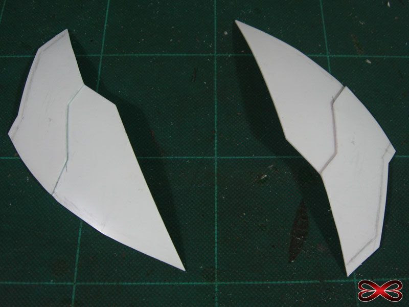
Instead of a single piece, each "feather" of the main wing is made of two pieces, cut and attached at a certain angle as such the lower layer "catches" the movement of the higher layer thereby creating a natural angle limiter between layers.

Posted Image

I made two prototypes, then decided to use the design of the larger one (keeping the prototype untouched, just in case) to match the Bathala's height. I then encased the joint portion with a simple "box" that follows the shape of the wing. The main wing's span is already at 29 cm, so this thing is going to be huge and heavy. I used all my remaining 1.0mm HIPS for these, since I noticed that even the 1.0mm tends to grow stiff and brittle over time.

Posted Image Posted Image Posted Image

Unlike in the Angelus, the Bathala has a lower compound wing with "feathers" that also fold in and out slightly. The feathers are compounded in a 4-3 configuration, each with its own articulation point.

Posted Image

A very "dry" test fit. This is how it should look like when the main and lower wings are attached.

Posted Image

Joining the Wings. Initially, I decided on a simple swivel mechanism to connect the main and lower wings, but that basically limited the Wing's swivel in one direction. I wanted the wing to swivel in several directions so that I can pose it folding over the shoulder of the Bathala somewhat, similar to that of the WingZC. I thought about this a lot, and the only way I can achieve this without making the joint too complicated was to use 8mm Revoltech Revolver ratchet joints. These joints are rare and very difficult to procure, and I got a few of these from R10 via M1Gs a couple of years back and haven't been able to use them, well, until now.

Posted Image Posted Image

Posted Image


With the Bathala's wing becoming heavy, I had to make sure that that joint's pegs can handle the weight (they're thin and actually soft, being made with High Density Polyethylene, a plastic similar to polycaps), so I made peg modules by encapsulating polycaps with HIPS and WHIPS. These not only hold the polycaps but reinforce them as well. I'm still deciding if I'll mount them permanently on their respective sections or have them removable.

Addendum (18 July 2012):

Lightning update. Though it's main purpose is to hold the main wing up, the lower wing also has semi-articulated compound feathers that swivel out for a full spread pose. This combines weight support functionality with wing aesthetics, so if I was thinking the same way I did before this would be very complicated.

Instead, I drew inspiration from the main wing of a jumbo jet. The mini-wings will be encased in a wing-shaped "box," and that in turn is constructed in such a way that it it becomes solid in itself without additional reinforcement. The final assembly has potential to be very heavy, so I had to reduce weight by removing material inside the "box." This is easily hidden with the layered armor, in which I also removed material covered by the overlapping layer.

Posted Image Posted Image Posted Image

Posted Image


I worked on the connective modules of the joint between the main and lower wings I'm still struggling with OC tendencies to make everything removable. The 8mm Revolver joint holds the wing in place at that angle, but I would have to deal with it spinning somewhat on the "axis" of the peg because of the overall weight.

Posted Image Posted Image

Posted Image


With this simple configuration, I was able to do the entire wing assembly in roughly 4-5 days, whereas, my previous (and somewhat failed) attempts took weeks, if not months, just figuring out the mechanisms.

Sunday, July 15, 2012

"BATHALA" - PMX-003 MG The O vMatX Part V

Symmetrical Solipsism. Symmetry is always a tricky matter especially when doing symmetrical parts at separate times. I started these at the same time, but, as it went, I had to redesign them to make them streamline. The problem wasn't avoiding having to redo the parts, but rather, making them symmetrical at mid-stage of the build. So I had to employ a few old tricks maybe a few of you already know.

We generally use masking tape to mask parts during painting, and maybe keep cemented parts in place as they bond and cure. But, I also use masking tape to achieve curved-parts symmetry by applying tape over the curved surface I want to replicate, marking the edges I want to copy with a pencil, then apply that over a slab of WHIPS (or plaplate). I then simply cut the part along the lines I've made, adjusting the cut as needed, then flip the cut part. With this technique, I can achieve very close symmetry with little room for error.

Posted Image Posted Image

Posted Image


Using the same masking tape technique, I outlined the main half-leaf shape. Since I've already braced the outer edge of the layered armor, and with the marking tape curving in instead of out, I have an extra millimeter or so to contend with with the replicated mirror-version of the armor. This can be adjusted later on.

Posted Image Posted Image

The rest is easy. All I had to do in this case is mirror the ribbing and connective parts.

Posted Image Posted Image

Posted Image


Then pencil marks are planned details, which most probably done with 0.5mm WHIPS.

Saturday, July 14, 2012

"BATHALA" - PMX-003 MG The O vMatX Part IV

Skirting by. I decided to modify the the front skirts to more appropriate proportions, reducing the width in the process. I cut the ball joints and one of the vent connections on each of the skirt frames, then cut the skirt armor along the length of the thicker section. I then cut the side section to remove a few millimeters. I then made a new connective framework by merging the connective ball joint with a shaped WHIPS, reinforced at the edge with 3mm beams. I then rebuilt the armor with WHIPS, maintaining the vent connector. These will undergo further detailing.

Posted Image Posted Image

Posted Image


I've also rebuilt the midsection of the the rear skirt by modifying a spare part from my PG Astray kit (coincidentally, this is also a rear skirt section) and modifying the frame to add shape, detail and volume overall. The assembly comes three sections for easier painting later on.

Posted Image Posted Image

Posted Image


Last but not least, I've decided to build the rear skirts entirely from scratch, mainly because the modified stock skirts seemed off, and any further modifications would be a waste of time. Unlike the Front skirts, I'll be making these in once-piece sections, mainly because of the curvature I need to accomplish.

Posted Image

Prototyping frustration
. Initially, the rear skirts looked nice to me, that is, until I've wrapped the top part. At this stage the flaws of my design bared its teeth, with the curves looking forced and uneven. I was going to simply cover it with my planned layered armor design, but that also posed a problem since even though it's a single piece, the thing got too heavy with all the thickening I had to do to get enough surface area on the edges for the curved surface to adhere to. So, I had to do a "quick" rethink.

Posted Image Posted Image Posted Image

At this point, I was already working on the layered armor for the initial design by curving shaped pieces of WHIPS. Without using heat, one can get a more spherical curve by combining smaller curved pieces. I prefer doing it this way since the armor is layered after all, and I can still make small adjustments later on.

Posted Image Posted Image

Posted Image


While I was working on the layered armor, I decided to make the darn thing a two-piece assembly. I used the initial failed skirt as a mold for the layered armor, removed the top ugly part, and kept the base as it was, made adjustments as needed and mounted 3mm beams (that will serve as connectors). I added "ribs" on the inside part of the armor, which doubles as connective stops for the frame base.

Posted Image Posted Image Posted Image

The original one piece skirt with the two-piece redesign side-by-side justified my frustration earlier on. Aside from having a better, streamlined shape, the two-piece assembly is actually lighter than the single piece without the layered armor.

Posted Image Posted Image Posted Image


I'm using WHIPS exclusively now (I still have a whole 1.0mm, cut 0.5mm and 0.3mm Tamiya plaplates), to test its useability. Compared to plaplates, WHIPS are sifter and easier to cut, shape and bend. Filing and sanding is also a non-issue, though the softness does take a bit of getting used to.

The Newbie Stash

Source This is a collection of specific guides for reference in Gunpla Building and Modeling in General.  • Gunpla™ and Modeling Terminolog...